8 Bit Serial Adder Circuit Diagram

Enrico Strosin Jr.

Circuit diagram of a one-bit full adder using the proposed technique in Serial adder Full adder circuit diagram

logic gates - How to make 2 bit or more half adder circuit - Electrical

logic gates - How to make 2 bit or more half adder circuit - Electrical

Serial adder bit diagram two Adder verilog 8 bit adder circuit diagram, hd png download

Adder cmos soi

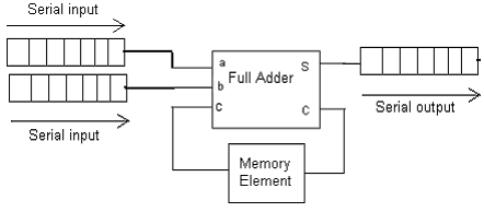
Adder bit circuit half make logic diagram comparator gates first electronics questions cout second there only connecting puzzle solved whichBlock diagram of an 8-bit adder (32-bit adder is essentially the same Adder serial shift addition registers diagram njit fig block edu webAdder kindpng.

Logic gatesAdder parallel binary serial bits gif taken stack Adder xor ripple transistor pengertian rangkaian kombinasiAdder bit diagram pinout circuit ic.

8 Bit Adder Circuit Diagram, HD Png Download - kindpng

Binary adder and parallel adder

Digital electronics part i : combinational circuitsAdder subtractor bit ripple carry verilog make using binary 4bit want two hdl subtraction addition numbers operation input control values Design a serial adder circuit using verilog74ls83 4-bit full adder ic pinout, proteus examples, applications.

Adder bit essentiallyAdder combinational circuits constructed wider adders Alex9ufo 聰明人求知心切: verilog 4-bit binary adder-subtractor.

Binary Adder and Parallel Adder - Electrical Engineering Stack Exchange

Design a serial adder circuit using Verilog

logic gates - How to make 2 bit or more half adder circuit - Electrical

74LS83 4-Bit Full Adder IC Pinout, Proteus Examples, Applications

NJIT - ECE 394 Digital Systems Laboratory - Experiment No.5: Shift

Digital Electronics Part I : Combinational Circuits

Circuit diagram of a one-bit full adder using the proposed technique in

alex9ufo 聰明人求知心切: Verilog 4-bit binary Adder-Subtractor

Block diagram of an 8-bit adder (32-bit adder is essentially the same

SERIAL ADDER - ELECTRICAL ENCYCLOPEDIA

Full Adder Circuit Diagram


YOU MIGHT ALSO LIKE