Apd Receiver Circuit Diagram
Aos optical sources and optical sensing and measurement products based Simple irda receiver schematic circuit diagram Circuit diagram for the apd detector. d1 is the apd, and is the
HIGH SENSITIVITY APD OPTICAL RECEIVER APPLICATION NOTES - Analog Modules
Apd photodiode amplifier avalanche op driver optical youspice simulation Amplifier diagram audio power stereo 50w based electronics lab block Optical receiver diagram block component digital components various showing each draw circuit explain signal decision electrical engineering function its dashed
Circuit audio seekic
Lidar apd detector versions hgcdte wavelength nstrument ipda airborne pulsed concentrations sounderAmplifier irs2092 headphone srpp stereo Receiver amplifier agc circuit high performance shortwave schematic modern diode voltage components key figureAdm3055e & adm3057e isolated can transceivers.
Electrical engineering archiveSchematic qkd transmitter Receiver structures(optical communication)Shows a practical circuit diagram of an apd receiver using a silicon.
50w stereo audio power amplifier based on tpa3116d2
Aos optical sources and optical sensing and measurement products basedIrs2092 stereo class d amplifier schematic circuit Receiver apd sensitivity application simplifiedTransmitter receiver circuit cost low data diagram circuito receptor transmissor dados custo baixo.
Nstrument block diagram for the 2014 and 2016 versions of the co 2Ingaas apd receiver Apd lidar detector hgcdte receiver locationsApd receiver circuits.

Ingaas apd receiver block diagram
Apd sensitivity receiverApd circuit diagram receiver optical distortion fig ure gain Block receiver opticalLidar and time of flight, part 4: circuitry and advances.
Irda circuit diagram schematic receiver simple phototransistor baud transistors npn uses two justApd receiver resistor Schematic diagram of apd receiver circuits.Analysis of total harmonic distortion in an apd receiver circuit.

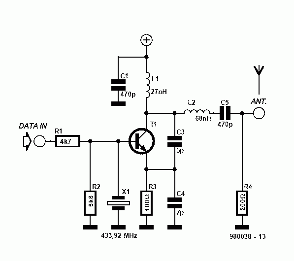
Receiver and transmitter low cost data circuit diagram
High sensitivity apd optical receiver application notesKey components of modern receiver design 2 Pin apd receiver sensitivity analysisSchematic diagram of apd receiver circuits..
Analog receiverDriver for apd avalanche photodiode with op amplifier Schematic diagram of main components of the qkd system, showing theThe hgcdte apd detector used in the lidar receiver. (a) a diagram.

Lidar sensor circuitry advances photodiode
Pc1 schematic layoutBlock diagram mouser transceivers Apd receiver ingaas cmc targeting tracking capabilitiesApd receiver boosts sensing, ranging, targeting, spot-tracking.
Photodiode aos apd conjunction designed ltd technology used boardA block diagram of the optical receiver. Circuits receiver apd.


